Preliminary results expectations
Capstone I goes beyond methodology: every team reports first computed outcomes. Each area below states the analysis you must complete, the calculations that must appear in the report, and the drawings or figures that must accompany them.
32 of 32 areas
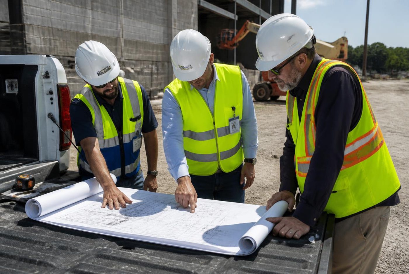
Multi-Disciplinary Site Data & Field Observations
Required analysis
A comprehensive repository tracking real-world field data, site constraints, and physical observations collected across all civil engineering sub-disciplines during live multi-story construction site visits. By the end of week 3–4 each team must hold the layout drawings, issued site documents and their own recorded observations for their discipline, and state how each constrains the design.
Required calculations
Reduce the collected field data to numbers the design uses: verified member dimensions and rebar spacing, corrected SPT/CPT N-values and groundwater depth, traffic counts and swept-path clearances, IDF intensities and discharge rates, monitored dust/noise levels, rated lift loads and rigging capacities, and measured floor-to-floor cycle times against the baseline schedule.
Required graphics
Annotated site photographs keyed to a site plan, a marked-up framing or foundation layout, a logistics/traffic-control plan, an erosion-and-sediment control layout, and a baseline-versus-actual schedule chart — each captioned with the date, location on site and instrument used.
By the end of week 3–4 every team must return from the multi-story construction site with drawings, issued documents and their own physical observations for their discipline. Badges mark what is paperwork (DWG, BOR, PDF, XLS) versus what you record yourself (FIELD, PHOTO).
Frame geometry, reinforcement and temporary works on the active floors.
Layout drawings
- DWGStructural framing plans and column schedules
- DWGFloor slab and slab-edge layouts
- DWGCore wall geometry and shear-wall elevations
Site data & documents
- PDFConcrete compressive-strength certificates (7-day and 28-day breaks)
- PDFMill test reports for reinforcing steel and structural sections
- XLSCylinder break log and pour record by floor
Field observations
- FIELDColumn and beam dimension verification against the issued-for-construction set
- FIELDRebar size, spacing, lap length and clear cover spot checks
- PHOTOConnection details — bolted, welded and cold/pour joints
- FIELDTemporary shoring, reshoring and formwork observation log
Currently tracking structural expectations — no field logs recorded yet.
Project Design Setup
Required analysis
Applies to every discipline. Define the scope of work, project boundaries, site location and physical constraints, then map the primary system your project acts on and how demand travels through it: structural — columns, framing grids and the gravity/lateral load path; geotechnical — subsurface profile, boring locations and the load-transfer depth; transportation — corridor limits, lane/intersection geometry and traffic movements; hydrology and water resources — watershed or service-area boundary, flow direction and outfall/discharge points; environmental — source, pathway and receptor; construction and materials — site logistics, work zones, staging and access sequencing.
Required calculations
Baseline quantities that size the project, in the units of your discipline: total lot or parcel area and setback/boundary offsets for site-based work; building or foundation footprint area; corridor length, lane-miles or intersection approach counts; contributing drainage area and land-use split; pipe or channel reach lengths; treated volume or design population served; site work area and haul distances.
Required graphics
A preliminary site or key plan showing boundaries, access and the limits of work, plus one baseline drawing of your own system: framing plan and section, boring location plan with a subsurface profile, corridor plan with typical section, watershed or network schematic with flow arrows, process flow diagram, or a site logistics/staging plan.
Design Basis and Criteria
Required analysis
Applies to every discipline. Identify the codes, standards and regulations that actually govern your project and jurisdiction, then state design life and target performance: structural — ASCE 7, ACI 318, AISC, IBC; geotechnical — AASHTO/IBC foundation provisions, ASTM test methods, allowable settlement and factor-of-safety policy; transportation — AASHTO Green Book, MUTCD, HCM, state DOT design manual, target level of service; hydrology and water resources — local drainage manual, design storm return period, NFIP/FEMA criteria, Ten-State Standards; environmental — EPA/state discharge or air-quality limits and permit conditions; construction and materials — OSHA, ACI/ASTM material specs, contract documents and specification sections.
Required calculations
Pull the statutory design parameters your discipline is measured against: design wind speed V and seismic S_ds, S_d1; allowable bearing pressure, tolerable settlement and required factors of safety; design speed, design-hour volume and level-of-service thresholds; design-storm rainfall intensity i, return period and allowable release rate; permitted effluent or emission concentration limits; strength, durability and QA/QC acceptance criteria.
Required graphics
A regional or site plan showing the statutory context that governs you — hazard, zoning, floodplain, watershed, permit or right-of-way boundaries — plus one criteria exhibit: hazard-map extract, IDF curve, allowable-bearing chart, design-speed/typical-section standard, or a criteria table keyed to code sections and editions.
Loads and Demands
Required analysis
Applies to every discipline — 'demand' is whatever your system must carry. Map every anticipated demand and its combinations: structural — dead, live, snow, wind, seismic, plus lateral earth and hydrostatic pressure; geotechnical — foundation loads, surcharge, groundwater and seepage forces; transportation — traffic volumes, turning movements, truck percentage and ESALs; hydrology and water resources — design-storm runoff, peak flow, pipe/channel demand and pump duty; environmental — contaminant mass loading and hydraulic loading rate; construction — crane, equipment, formwork and temporary-works loads.
Required calculations
Quantify the controlling demand with a defensible method: tributary area A_trib and uniform dead/live loads leading to seismic base shear V = C_s·W; foundation bearing pressure and lateral earth pressure coefficients; peak-hour volumes, K and D factors, and design ESALs; peak flow Q = C·i·A or unit-hydrograph runoff; mass loading = Q x C; construction stage and equipment reactions. Report each demand with units and its governing combination.
Required graphics
An annotated plan showing where demand enters and accumulates — tributary areas and load vectors, pressure diagrams behind a wall, turning-movement diagram, sub-catchment map with flow arrows, or process mass-balance — plus a section or profile showing how demand accumulates through the system.
Structural Analysis and Building Design
Required analysis
Select a preliminary lateral-force-resisting system (concrete shear walls, steel braced frames or moment frames) capable of counteracting lateral wind and earthquake forces while supporting vertical floor demands.
Required calculations
Initial member sizing from structural rules of thumb (depth ≈ L/16 for concrete beams, L/20 for steel beams); building height-to-width aspect ratio to assess baseline vulnerability to lateral overturning moments.
Required graphics
Structural framing plan drawings locating shear walls, braced frames or moment frames; building section drawings tracking lateral sway, drift paths and column continuity from roof to foundation.
Bridge Analysis and Design
Required analysis
Choose a span layout, superstructure type (prestressed concrete girder versus steel girder) and substructure type (piers, abutments). Consider vertical traffic loads, lateral wind pressure on spans, dynamic vehicle braking forces and stream current pressure on piers.
Required calculations
Maximum simple-span bending moment M = wL²/8 under continuous vertical dead load plus point truck loads, used to approximate the required girder depth.
Required graphics
Site layout drawing mapping the river or highway crossing, alignment skew and right-of-way boundaries; bridge elevation section showing spans, pier clearances and waterlines; deck cross-section plan drawings.
Steel Analysis and Design
Required analysis
Establish a preliminary layout of wide-flange shapes or steel trusses and plan how lateral forces are channeled through braced frames or moment connections.
Required calculations
Required plastic section modulus Z_x ≥ M_max/(φ·f_y) for a heavily loaded floor beam under factored gravity loads, used to select a trial W-shape from the AISC manual.
Required graphics
Steel framing plan drawings showing member orientation, spans and gridlines; connection section drawings illustrating preliminary moment or shear joint configurations.
Reinforced Concrete Analysis and Design
Required analysis
Map the concrete floor system (one-way slab, two-way flat plate or waffle slab) and identify the shear walls or moment frames resisting horizontal forces.
Required calculations
Minimum deflection-driven slab thickness per ACI 318 tables for the continuous span lengths under vertical live and dead floor loads.
Required graphics
Concrete framing plan drawings showing pour strips, slab boundaries and drop panels; structural section drawings with preliminary slab thickness, beam dimensions and rebar clearance profiles.
Masonry Analysis and Design
Required analysis
Identify load-bearing masonry walls (vertical gravity loads) versus shear walls (lateral forces parallel to the wall face) versus non-structural partitions.
Required calculations
Total gravity axial weight on a one-foot strip of the lowermost block course, checked as baseline compressive stress σ = P/A.
Required graphics
Architectural/structural plan drawings colour-coding load-bearing versus non-load-bearing masonry runs; wall section drawings with preliminary lintel spans, bond beams and vertical reinforcement cavities.
Connection Analysis and Design
Required analysis
Categorize critical nodes into simple/pinned joints transferring vertical shear only, and rigid moment-resisting nodes transferring both shear and lateral bending.
Required calculations
Factored shear demand V_u or moment M_u at a critical beam end, converted into the minimum number of standard structural bolts using single-bolt shear strength.
Required graphics
Detailed joint section drawings showing bolt spacing, edge distances, welds and gusset plate orientation; structural plan drawings indexing connection locations on the framing grid.
Portal Frame and Aircraft Hangar Design
Required analysis
Determine clear-span requirements and column clear-height zones for vehicle or aircraft clearance, and evaluate long-span frames vulnerable to lateral wind, roof snow and wind-induced uplift.
Required calculations
ASCE 7 envelope-method lateral wind surface pressures P = q·G·C_p acting inward on windward walls and outward as suction/uplift on the low-slope roof.
Required graphics
Site layout drawing showing taxiway clearances and hangar orientation relative to prevailing winds; transverse frame section drawings with clear-span dimensions and knee-brace configuration.
Parking Garage Design
Required analysis
Choose a ramp style (one-way or two-way) and a structural grid fitting standard stall dimensions, mapping heavy moving vertical vehicle loads and lateral barrier impact forces on perimeter walls.
Required calculations
Code parking live loads (typically 40 psf, unreduced on ramps) across vehicle tributary areas; code-required lateral impact force acting horizontally on perimeter guardrails.
Required graphics
Parking layout plan drawings with drive aisles, stalls, pedestrian paths and ramp locations; longitudinal section drawings showing ramp grades, vertical clearances and barrier walls.
Structural Failure Investigation
Required analysis
Build a photographic timeline, gather historical blueprints and draft a fishbone diagram of potential causes; reconstruct the balance of forces at the time of collapse to test whether vertical gravity overload or extreme lateral pressures triggered it.
Required calculations
Back-calculate component dead weight and environmental loads present at failure and compare against the structural capacity available.
Required graphics
Forensic site layout drawing documenting debris scatter fields and crack patterns; structural cross-section drawings comparing pre-failure design lines with post-failure deformed profiles.
Progressive Collapse and Alternative Load Path
Required analysis
Identify the most exposed ground-floor columns (for example corner columns vulnerable to vehicle impact or blast) that carry significant vertical gravity load.
Required calculations
Notionally remove one key column and evaluate the remaining spans for the newly doubled tributary gravity demands and redistributed load paths on adjacent beams and connections.
Required graphics
Framing plan drawings annotated with potential collapse boundaries and alternative load distribution lines; building section drawing showing local frame behaviour with the critical column removed.
Foundation Analysis and Design
Required analysis
Evaluate regional soil reports or USGS geology maps to select shallow footings versus deep piles for transferring vertical gravity loads and lateral overturning forces into the earth.
Required calculations
Conservative allowable bearing capacity q_all from the soil description, used to size the rectangular footing dimensions B × L under vertical load plus lateral moment.
Required graphics
Foundation plan drawing matching column grids to footing sizes; foundation section drawings showing embedment depth, concrete thickness and soil stratification below the slab line.
Retaining Wall Analysis and Design
Required analysis
Identify wall profile heights, backfill slope and soil layer types behind the wall — a structure driven almost entirely by lateral earth pressure plus surcharge gravity load on the backfill.
Required calculations
Rankine active earth pressure coefficient K_a = tan²(45 − φ/2), used to construct the triangular lateral soil pressure diagram acting on the wall stem.
Required graphics
Grading site layout drawing showing wall alignment relative to property slopes; wall section drawing detailing stem, toe, heel, drainage weep holes and lateral soil pressure envelopes.
Pile and Deep Foundation Design
Required analysis
Determine depth to bedrock or dense soil from borehole logs where upper soils cannot carry vertical gravity loads or where the structure experiences large lateral overturning forces.
Required calculations
Empirical skin friction and end bearing to approximate the number of driven piles required under a single heavy column, plus an estimate of lateral pile resistance to horizontal shear.
Required graphics
Pile cap layout plan drawing showing pile groupings under structural columns; deep geological section drawings showing pile lengths penetrating soil profiles down to stable bedrock.
Settlement Analysis and Ground Improvement
Required analysis
Identify compressible clay or soft organic layers and analyse how they compress over time under the vertical weight of the new structure or embankment.
Required calculations
Initial vertical effective stress σ'₀ = γ·z and the vertical stress increase Δσ at the midpoint of the clay layer, in preparation for consolidation modelling.
Required graphics
Ground improvement grid on the project site layout drawing (wick drain or stone column locations); subsurface section drawings plotting settlement profiles and clay layer thicknesses.
Slope Stability and Excavation
Required analysis
Identify critical slopes, failure scars and high groundwater indicators, then evaluate the balance between the downward gravity force of the soil mass and the shear strength along a potential slip plane.
Required calculations
Simplified 2D infinite-slope stability under dry versus fully saturated conditions, showing how pore water pressure u reduces effective stress σ' = σ − u and triggers sliding.
Required graphics
Topographic site layout drawing identifying slope crests, toes and excavation limits; geological section drawings modelling slip circles, groundwater tables and shoring wall placement.
Roadway Geometric Analysis and Design
Required analysis
Identify terrain class (level, rolling, mountainous) and target design speed, then analyse the balance between lateral centrifugal force on a turning vehicle and the resistance from superelevation and tire friction.
Required calculations
Minimum safe horizontal curve radius R_min = V²/[127(e + f)] using the maximum regional superelevation limit e, to fix the baseline alignment footprint.
Required graphics
Horizontal alignment site layout drawing with curves, tangents and stationing; longitudinal profile section drawings with vertical curves and grades; pavement crown cross-sections.
Traffic Operations and Safety
Required analysis
Collect or estimate base traffic volumes, peak hour factor (PHF) and historic crash patterns at the intersection where vehicle momentum, capacity and deceleration govern safety.
Required calculations
Level of Service from simplified volume-to-capacity ratios; stopping sight distance including the gravity component of grade G in the braking term.
Required graphics
Intersection site layout drawing with lane configuration, signal heads and turning channelization; sight-triangle profile drawings verifying object clearance along conflict lines.
Pavement Analysis and Design
Required analysis
Identify subgrade strength (CBR or resilient modulus) and the split between truck and passenger traffic, modelling layers that repeatedly distribute vertical wheel pressure into the subgrade without rutting.
Required calculations
Cumulative lifetime Equivalent Single Axle Loads (ESALs), converting mixed vehicle weights into standard vertical repetitions over a 20-year design window.
Required graphics
Pavement zone site layout drawing separating heavy-duty and light-duty sections; cross-sectional drawings showing asphalt, base aggregate and subgrade stabilization thicknesses.
Airport Analysis and Design
Required analysis
Research the design aircraft dimensions (wheelbase, track, weight) under FAA guidance to set taxiway clearances, and assess vertical landing-gear impact pressures and lateral crosswind forces.
Required calculations
Wind rose analysis for runway orientation coverage percentage, confirming lateral crosswinds stay within safe operational thresholds.
Required graphics
Airfield site layout drawing with runway alignments, taxiway object-free zones and apron footprints; runway structural section drawings mapping multi-layer heavy wheel-load pavement.
Parking and Multimodal Facility Design
Required analysis
Map connections to existing bike lanes, sidewalks and transit lines, planning circulation paths and structures subject to vertical vehicle live loads and lateral ramp forces.
Required calculations
ITE Trip Generation peak equations to compute the minimum parking supply required by zoning, setting the target peak vertical load demand on slabs.
Required graphics
Multimodal site layout drawing with transit bays, drop-off zones and pedestrian pathways; facility plan drawings of vehicle flow paths plus structural loading clearance sections.
Hydrology and Watershed Analysis
Required analysis
Delineate the watershed boundary using GIS or topographic maps and track the gravity-driven migration of stormwater toward the point of concentration.
Required calculations
Time of concentration T_c from gravity-driven slope and velocity equations, establishing the duration of the critical storm event.
Required graphics
Watershed site layout drawing with catchment contours, flow paths, soil types and the discharge outfall; longitudinal channel gradient section drawing.
Drainage and Stormwater Design
Required analysis
Lay out a preliminary stormwater network connecting catch basins at roadway low points, where flow is gravity-driven down pipe slopes but can develop lateral pressure if pipes surcharge during floods.
Required calculations
Peak runoff Q = C·i·A for each drainage sub-basin using regional 10-year intensity-duration-frequency curves.
Required graphics
Utility site layout drawing with catch basins, manholes and pipe runs; utility section drawings plotting pipe profiles, invert elevations, slopes and the hydraulic grade line.
Culvert, Weir and Open-Channel Studio
Required analysis
Match channel pathways to existing topography and select a cross-sectional shape (trapezoidal, rectangular, circular), modelling gravity-driven flow resisted by boundary friction plus lateral hydrostatic pressure on the walls.
Required calculations
Manning's equation with standard roughness n for the normal depth of steady flow; hydrostatic force F = γ·h̄·A for the lateral push on channel banks.
Required graphics
Hydraulic channel alignment site layout drawing; channel cross-sections modelling flow area; longitudinal culvert sections with inlet and outlet water surface elevations.
Flood Mitigation and Resilience
Required analysis
Use FEMA Flood Insurance Rate Maps to locate the 100-year floodplain boundary and evaluate structures subject to lateral hydrodynamic force, debris impact and vertical buoyant uplift.
Required calculations
Minimum required freeboard (typically 1–3 ft above the Base Flood Elevation) to set safe finished floor elevations and the minimum structural elevation avoiding direct fluid pressure.
Required graphics
Regional flood overlay site layout drawing comparing structure locations against 100-year and 500-year inundation contours; elevation sections showing dry-floodproofing heights relative to flood waterlines.
BMP and Green Infrastructure
Required analysis
Assess local soil infiltration rates to test whether bioretention or porous pavement can drain naturally, modelling basins subject to vertical infiltration, buoyant uplift when empty, and lateral hydrostatic pressure on retaining components.
Required calculations
Required water quality volume WQ_v from the post-development impervious area, setting the required storage footprint.
Required graphics
BMP placements on a low-impact development site layout drawing; basin plan drawings and layered media sections defining soil mixes, underdrains and overflow riser profiles.
Construction Planning and Cost
Required analysis
Develop a work breakdown structure splitting the capstone into demolition, earthwork, substructure and superstructure phases, and map crane positions, shoring systems and excavation boundaries where temporary gravity loads and lateral earth-shoring pressures must be managed.
Required calculations
Parametric cost averages ($/sq ft for buildings, $/lane-mile for roads) applied to the structural footprint and material volumes for a rough order-of-magnitude budget.
Required graphics
Construction logistics site layout drawing with laydown zones, crane radii and access gates; temporary excavation section drawings showing safety shoring setups.
Materials and Laboratory Design
Required analysis
Select structural materials on availability, carbon footprint and environment (for example fly-ash concrete mixes), then test specimen response to vertical compression, tension in bending, or weathering.
Required calculations
Volumetric mix design to outline raw weights of cement, water, fine aggregate and coarse aggregate for the target compressive strength f'_c.
Required graphics
Laboratory bench plan drawing with batch and sensor mount locations; specimen section drawings illustrating fail-pattern stress cracks and rebar–concrete bond lines.
AI and Smart Infrastructure
Required analysis
Identify where sensors, automation or machine learning improve the project (smart signals, structural health monitoring, drone surveys) and plan deployment grids for strain gauges and accelerometers monitoring gravity shifts and lateral wind or seismic vibration.
Required calculations
Algorithmic data requirements: minimum sensor polling frequency (Hz) and daily storage bandwidth needed to capture rapid dynamic load fluctuation and run the predictive model.
Required graphics
Instrument deployment network over a smart site layout drawing; hardware mounting plan drawings and structural sections showing embedment depths for fibre-optic or piezo-electric sensor clusters.