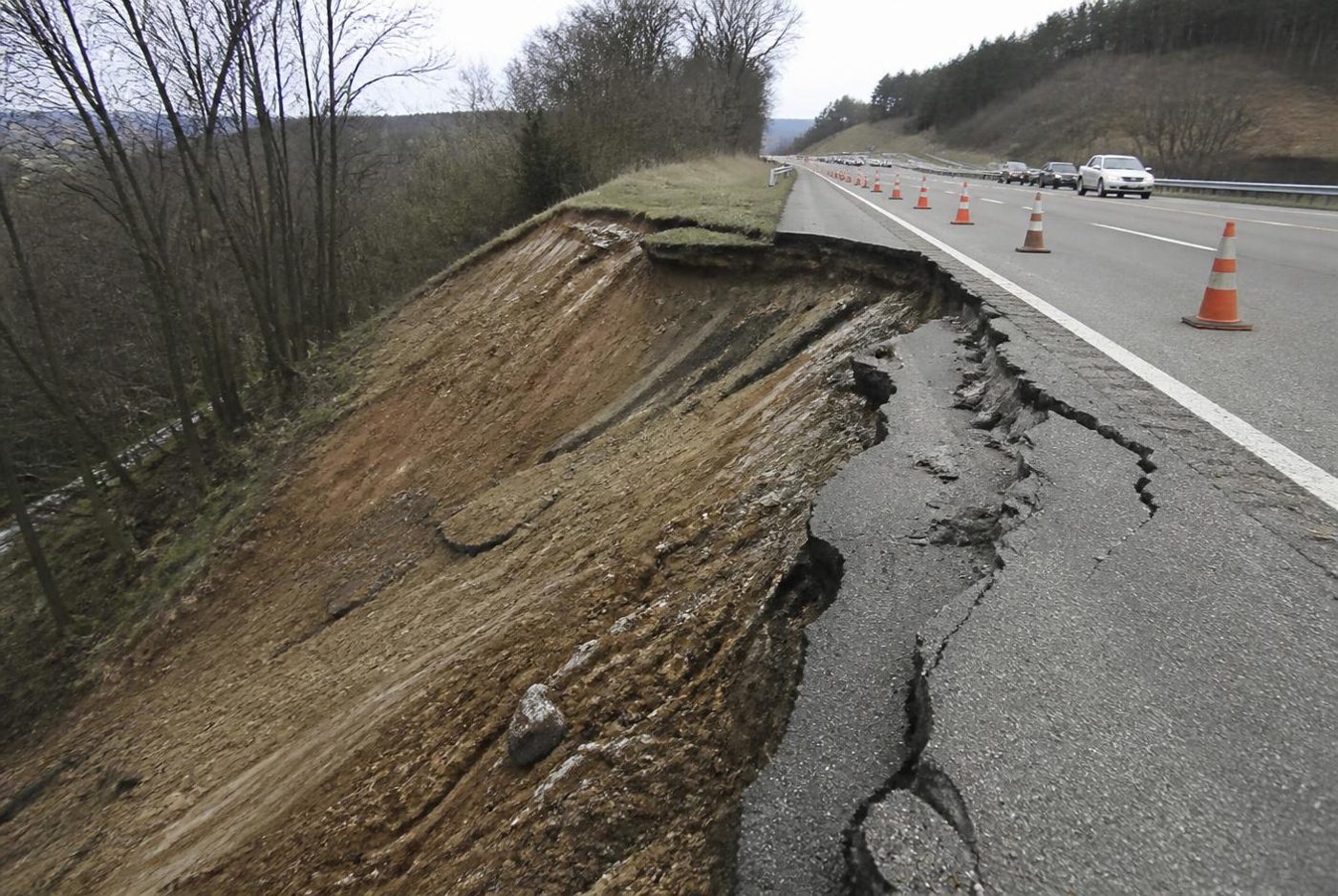

Failure Investigations
Timeline, failure sequence, structural analysis, redesign, and lessons — with proposal ideas.
Hyatt Regency Walkway Collapse
1981 · Steel connections / design review114 killed, 216 injured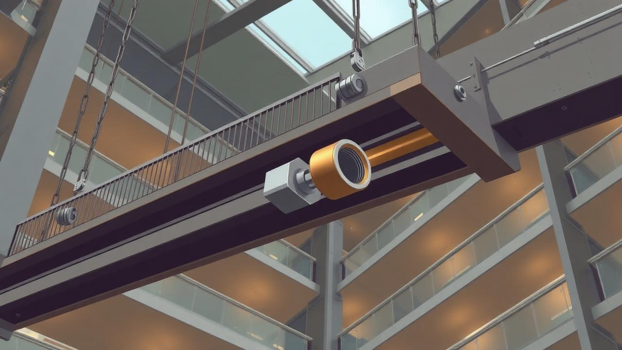
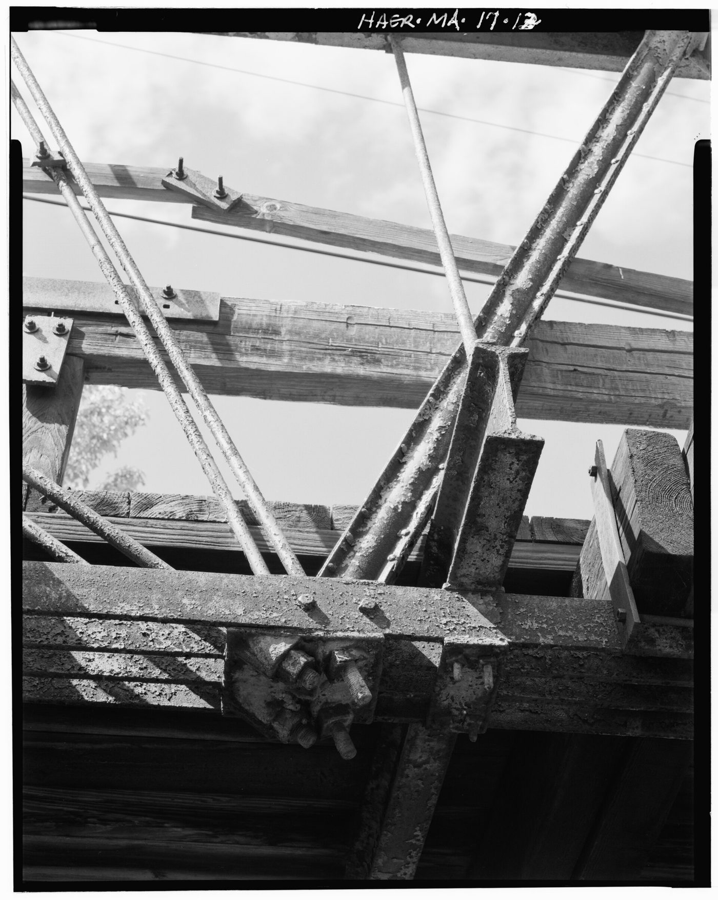
Timeline
- 1978 — Design: fourth-floor walkway hung from continuous rods through the second-floor box beams.
- 1979 — Shop drawing change: single continuous rod replaced by two offset rods.
- 1979 — Change accepted without independent structural review.
- 17 Jul 1981 — Tea dance; walkways loaded with spectators; connection fails.
Failure sequence
- Load from the fourth-floor walkway transferred into the second-floor box beam connection.
- The revised detail doubled the load on the upper box beam washer/nut bearing.
- The box beam welded seam tore; the nut pulled through the beam flange.
- Fourth-floor walkway fell onto second-floor walkway; progressive collapse to the lobby.
Structural analysis
- Original detail: box beam carries load of one walkway ≈ P.
- Revised detail: upper box beam carries its own walkway plus the hanger reaction from below ≈ 2P.
- Capacity of the welded box beam seam ≈ 0.6 × required for the original load — roughly 30% of the revised demand.
- Even the original detail did not meet the Kansas City code; the change made it catastrophic.
Redesign
- Use a continuous rod so each box beam carries only its own walkway load.
- Provide a bearing plate/stiffened seat sized for the full hanger reaction, not just washer bearing.
- Check local flange bending, weld strength, and block-type tearout at the rod penetration.
- Require engineer-of-record review and stamped calculations for any connection change.
Lessons learned
- Shop-drawing changes are design changes.
- Load path must be re-traced after every detail modification.
- Connection design is not a delegated afterthought.
Proposal ideas
- Digital shop-drawing change-tracking workflow with automatic load-path re-check
- Survey of connection review practice in regional fabrication shops
FIU Pedestrian Bridge Collapse
2018 · Concrete truss / construction staging6 killed, 10 injured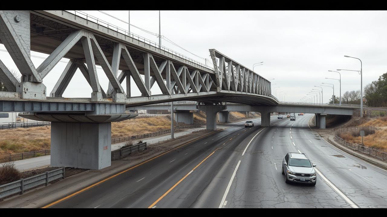
Timeline
- 10 Mar 2018 — Span moved into place using self-propelled modular transporters.
- 13 Mar 2018 — Cracking observed and photographed at node 11/12.
- 15 Mar 2018 — Post-tensioning in diagonal 11 re-tensioned; span collapses onto traffic.
Failure sequence
- Nodal region 11/12 had insufficient interface shear capacity between diagonal and deck.
- Cracks widened after the span was moved and the temporary supports removed.
- Re-tensioning increased demand on the already-cracked node.
- Interface shear failure → the diagonal punched through the deck → total collapse.
Structural analysis
- Interface shear demand at node 11/12 exceeded ACI 318 shear-friction capacity by roughly a factor of 2.
- Shear-friction: Vn = μ Avf fy; the roughened area and crossing reinforcement provided were inadequate.
- Redundancy was zero — a single concrete truss with no alternate load path.
- Structure was not closed to traffic despite visible structural cracking.
Redesign
- Increase interface reinforcement across the node and provide an intentionally roughened, keyed interface.
- Provide redundancy (two trusses or a supplemental support system) for the erection condition.
- Independent peer review of every construction stage, not just the final condition.
- Mandatory road closure protocol when structural cracking is observed.
Lessons learned
- Cracks are data, not cosmetics.
- The erection condition can govern.
- Non-redundant structures need higher review standards.
Proposal ideas
- Construction-stage structural monitoring protocol for accelerated bridge construction
- Shear-friction capacity study of node regions in concrete trusses
I-35W Mississippi River Bridge
2007 · Steel truss / gusset plates13 killed, 145 injured
Timeline
- 1967 — Built; U10 gusset plates detailed at 1/2 in thickness.
- 1977–1998 — Deck widened and re-decked, adding dead load.
- 1 Aug 2007 — Construction materials staged over U10; bridge collapses during rush hour.
Failure sequence
- Undersized U10 gusset plates carried increased dead load.
- Construction staging added ~578 kips over the critical node.
- Gusset plate buckled in shear/compression.
- Non-redundant deck truss collapsed completely.
Structural analysis
- Required gusset thickness ≈ 1 in; provided 0.5 in — a design-office error carried for 40 years.
- Demand-to-capacity at U10 ≈ 2.0 at the time of collapse.
- Gusset plates were not checked in routine inspections — inspections looked for corrosion and fatigue cracks.
- Fracture-critical, non-redundant configuration meant no alternate load path.
Redesign
- Thicken gusset plates and check Whitmore section, buckling, block shear, and net section rupture.
- Add redundancy or classify and inspect as fracture-critical with gusset-specific checks.
- Control construction staging loads with an engineered load-management plan.
Lessons learned
- Original design errors can hide for decades.
- Inspection scope must match the actual failure modes.
- Staged construction loads need engineering review.
Proposal ideas
- Gusset plate capacity screening of state-owned deck truss bridges
- Load-management protocol for construction staging on non-redundant bridges
Champlain Towers South (Surfside)
2021 · RC flat plate / durability98 killed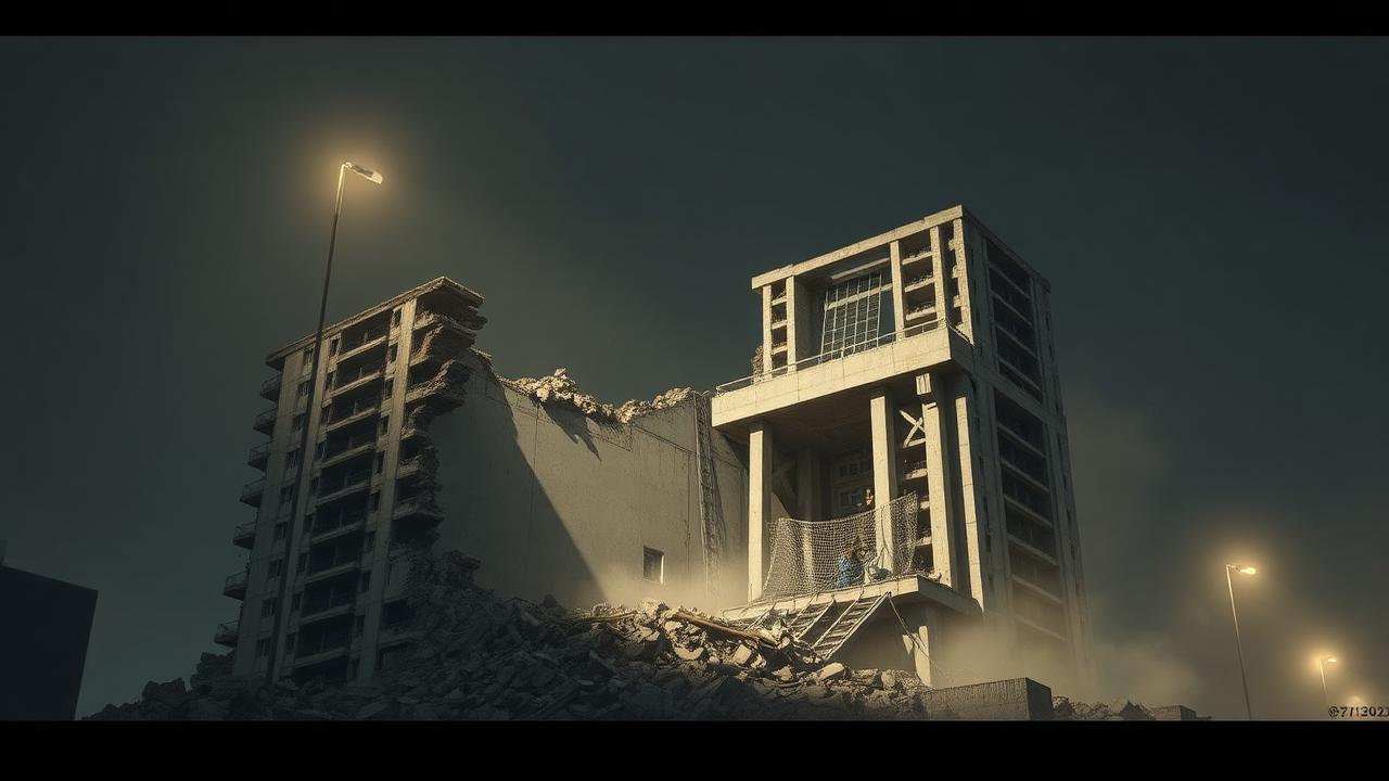
Timeline
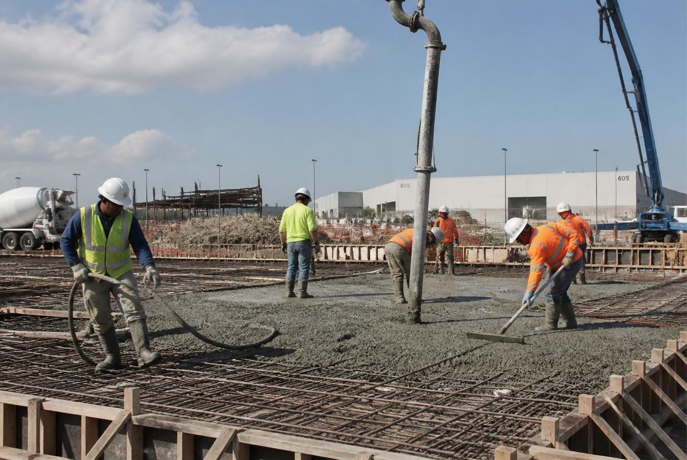
- 1981 — Constructed with a pool deck flat slab over the garage.
- 2018 — Engineering report documents major structural damage and failed waterproofing.
- 2021 — Repairs not yet executed; the building collapses at 1:22 a.m.
Failure sequence
- Chronic water intrusion through failed pool-deck waterproofing.
- Corrosion of slab and column reinforcement, section loss at the slab-column interface.
- Punching shear failure at pool-deck/column connections.
- Progressive collapse propagated into the tower.
Structural analysis
- Pool deck slab reportedly lacked required punching-shear capacity even as-built (low slab thickness, misplaced top steel).
- Punching: vu at the critical perimeter d/2 exceeded φvc after corrosion-related section loss.
- No structural redundancy in a flat-plate system once punching initiates — failure is brittle and propagates.
- Deferred maintenance turned a durability problem into a strength problem.
Redesign
- Provide shear studs/stirrups or drop panels at slab-column connections.
- Design waterproofing as a structural durability element with a maintenance plan.
- Increase cover and use corrosion-resistant reinforcement in wet exposure classes.
- Mandatory structural recertification with enforcement teeth.
Lessons learned
- Durability failures become strength failures.
- Flat plates are punching-shear critical and non-redundant.
- Reports without executed repairs save no one.
Proposal ideas
- Punching-shear vulnerability screening of aging coastal flat-plate garages
- Chloride-ingress service-life modeling for pool decks over occupied space
Tacoma Narrows Bridge
1940 · Aeroelasticity / suspension bridgesNo human deaths (one dog)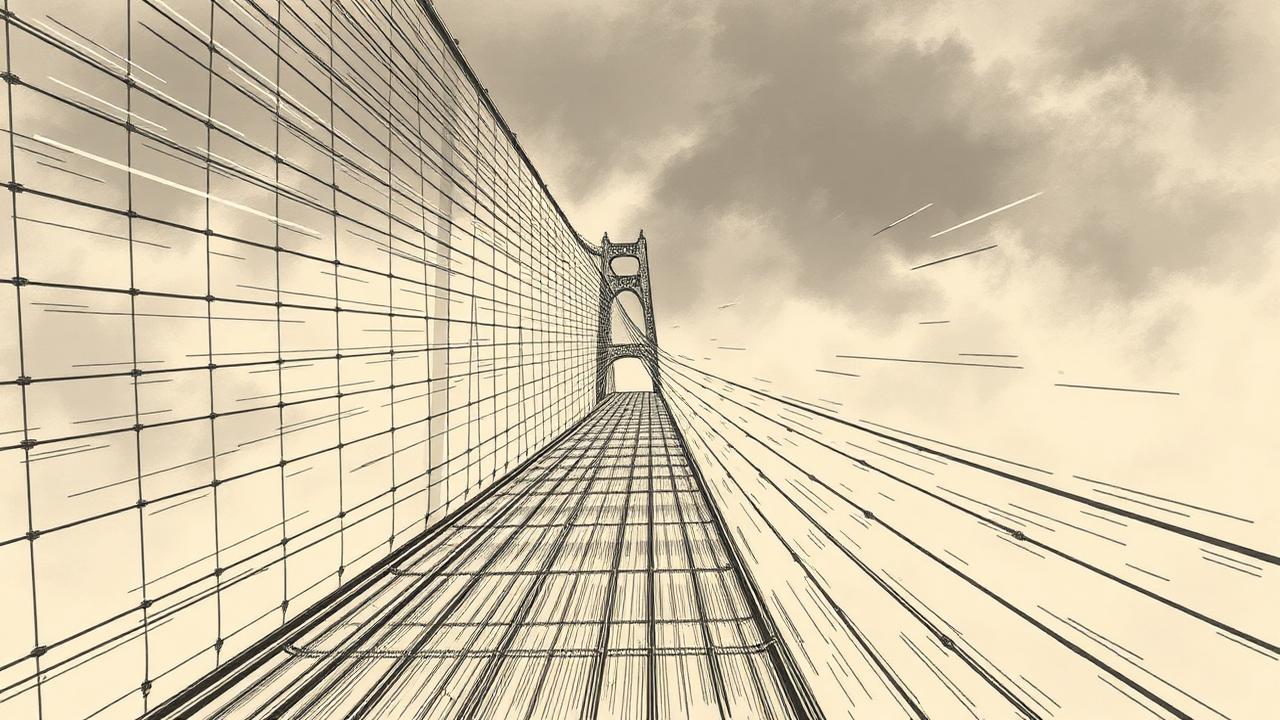
Timeline
- 1940 Jul — Opened; immediate vertical oscillation observed ('Galloping Gertie').
- 7 Nov 1940 — 40 mph wind induces torsional flutter; deck fails after ~70 minutes.
Failure sequence
- Shallow, solid plate girder deck with very low torsional stiffness.
- Wind produced self-excited aeroelastic flutter (not simple resonance).
- Torsional amplitude grew until the deck and hangers failed.
Structural analysis
- Deck depth/span ratio 1:350 versus contemporary practice ~1:100 — extremely flexible.
- Solid girders shed vortices and prevented pressure equalization; an open truss would have vented.
- Flutter is a negative-damping instability: energy input from wind exceeds structural damping.
Redesign
- Open stiffening truss deck with wind grating for pressure equalization.
- Increase torsional stiffness (closed box or truss).
- Wind tunnel testing of section models — now standard practice.
Lessons learned
- Slenderness driven by aesthetics/economy can create dynamic instability.
- Wind tunnel testing became mandatory for long spans.
- Flutter ≠ resonance.
Proposal ideas
- Section-model wind study for a proposed long-span pedestrian bridge
Silver Bridge
1967 · Eyebar chain / fracture46 killed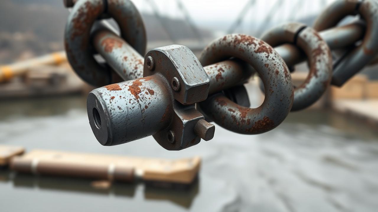
Timeline
- 1928 — Built as an eyebar-chain suspension bridge.
- 15 Dec 1967 — Rush-hour traffic; a single eyebar fails; the bridge drops in under a minute.
Failure sequence
- Stress corrosion cracking / corrosion fatigue in eyebar 330 at the pin hole.
- A 0.1-in defect grew to critical size.
- Non-redundant two-eyebar chain: one failure released the entire chain.
Structural analysis
- Fracture mechanics: Kc reached at a crack depth of roughly 0.12 in for the eyebar steel and stress level.
- The crack was internal to the pin joint and invisible without disassembly.
- Two-bar chain means zero redundancy — the definition of fracture critical.
Redesign
- Use multi-bar chains or cable systems with redundancy.
- Design for inspectability; avoid concealed fracture-critical details.
- Select tougher steels and control stress ranges.
Lessons learned
- Created the U.S. National Bridge Inspection Standards (1971).
- Redundancy and inspectability are design requirements.
Proposal ideas
- Inspectability scoring method for fracture-critical members in a state inventory
Mianus River Bridge
1983 · Pin-and-hanger assemblies / drainage3 killed, 3 injured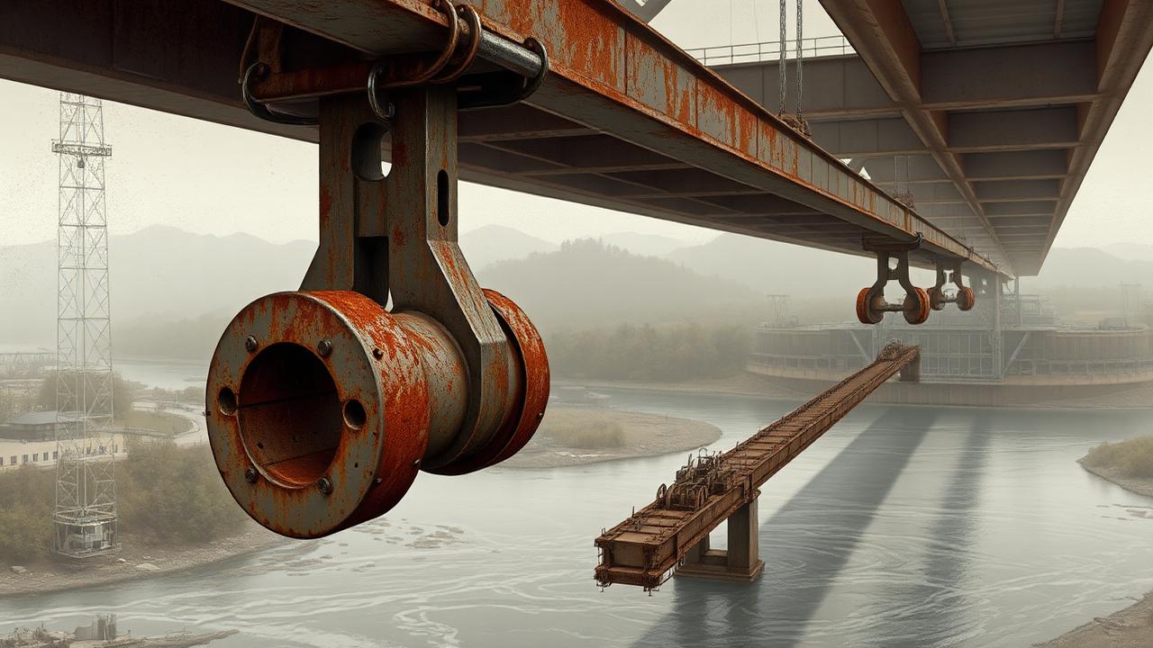
Timeline
- 1958 — Built with pin-and-hanger suspended spans.
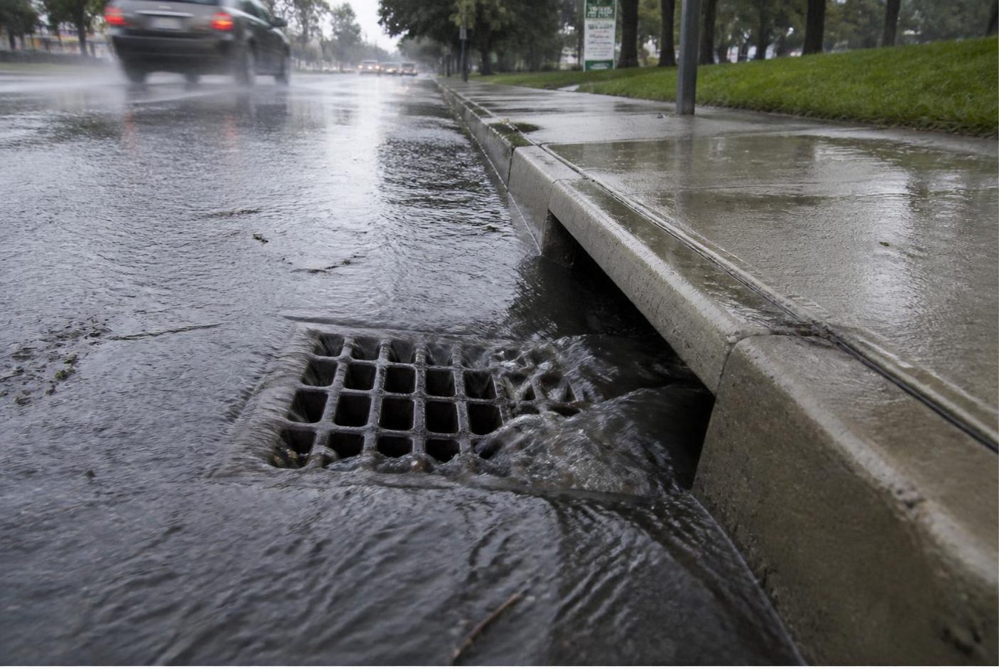
- 1970s — Deck drains paved over; water discharged onto the hanger assemblies.
- 28 Jun 1983 — Suspended span drops into the river.
Failure sequence
- Corrosion product buildup in the pin-and-hanger assembly forced the hanger outward.
- The outside hanger slipped off the pin.
- The remaining connection was overloaded and fractured; the span fell.
Structural analysis
- Corrosion 'rust packing' generated enormous lateral force on the hanger.
- Assembly was non-redundant and difficult to inspect.
- Blocked drainage was the initiating maintenance failure.
Redesign
- Eliminate pin-and-hanger details or provide catcher beams.
- Design and maintain deck drainage away from all steel details.
- Provide inspection access to every load-carrying connection.
Lessons learned
- Maintenance decisions are structural decisions.
- Detail selection determines lifetime inspection cost.
Proposal ideas
- Retrofit catcher-beam design for remaining pin-and-hanger bridges in the region